Complete website build including:
- Build Your Kit store page with cart system, sectioned layout
  (Hardware, Software, Attachments, Spare Parts), inline quote
  request form, and sticky sidebar summary
- 16+ pages: Education, Platform, Resources, News, About Us,
  Download, Contact, Rover, Code Editor, Robot Simulator, etc.
- 89+ MDX resource articles and 18 news posts
- Store product images scraped from micromelon.com.au
- Quote request API route with Airtable integration
- Dynamic back links and cover photos on resource pages
- Redesigned downloads page
- Fixed corrupted MDX code blocks
92 lines
3.8 KiB
Plaintext
92 lines
3.8 KiB
Plaintext
---
|
|
title: "Showcase: Rover and Arduino Line Follow"
|
|
date: "2024-12-30"
|
|
categories: ["Customer Stories"]
|
|
tags: ["Extension"]
|
|
excerpt: "Using I2C and an Arduino Nano, a QTR-8RC line sensor array can be attached to the Rover to undertake advanced line follow. This guide is a showcase of how this can be done.An overview of the I2C protocol and how to use it with the Rover can be found"
|
|
featuredImage: "/images/resources/showcase-rover-and-arduino-line-follow.JPG"
|
|
---
|
|
|
|
Using I2C and an Arduino Nano, a QTR-8RC line sensor array can be attached to the Rover to undertake advanced line follow. This guide is a showcase of how this can be done.
|
|
|
|
An overview of the I2C protocol and how to use it with the Rover can be found here.
|
|
|
|

|
|
|
|
## The Sensor (QTR-8RC)
|
|
|
|
The [Pololu QTR-8RC](https://www.pololu.com/product/961) is an array of 8 infrared sensors spaced approximately 9.5cm apart. The advantage of using 8 sensors for line following is that the robot's speed can be significantly increased as there is a much lower chance of losing the line when moving. When paired with the [QTR library](https://github.com/pololu/qtr-sensors-arduino/tags), the sensor array can calculate the line's location relative to it, returned as a value between 0 and 8000. If the line is lost, the sensor also can remember the last sensor that saw the line in the array.
|
|
|
|

|
|
|
|
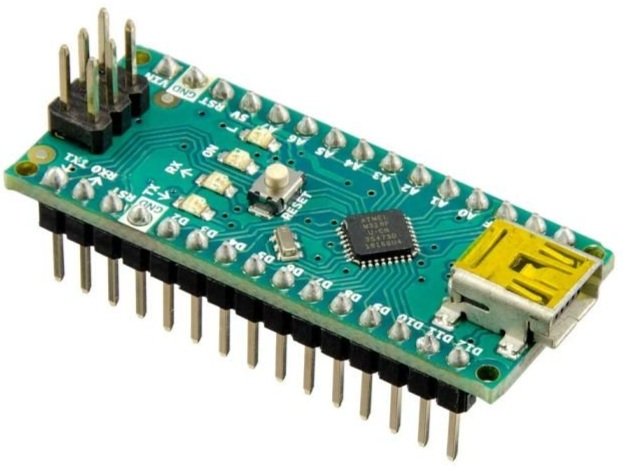
## The Arduino:
|
|
|
|
|
|
|
|
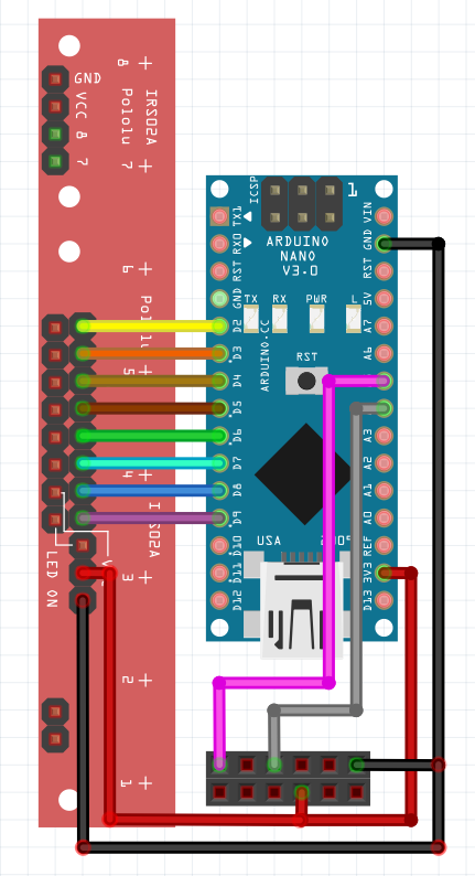
The Arduino Nano is the microcontroller used to control the QTR sensor. With the sensor plugged in, the Arduino uses the QTR library to locate the line's position under the sensor. The Arduino can then communicate with the Rover through the I2C communication protocol. The Rover requests data and receives a buffer containing the line's location determined by the infrared sensor array. This buffer is 2 bytes large because the maximum returned value of 8000 is larger than what a single byte can hold.
|
|
|
|
Further information on the code and the wiring diagram can be found below.
|
|
|
|
```
|
|
#include `<QTRSensors.h>`
|
|
#include `<Wire.h>`
|
|
|
|
#define ADDRESS 10
|
|
QTRSensors qtr;
|
|
|
|
const uint8_t SensorCount = 8;
|
|
uint16_t sensorValues[SensorCount];
|
|
|
|
uint16_t position = 2000;
|
|
void setup()
|
|
{
|
|
Wire.begin(ADDRESS);
|
|
Wire.onRequest(readSensor);
|
|
// configure the sensors
|
|
qtr.setTypeRC();
|
|
qtr.setSensorPins((const uint8_t[]){9, 8, 7, 6, 5, 4, 3, 2}, SensorCount);
|
|
|
|
delay(500);
|
|
pinMode(LED_BUILTIN, OUTPUT);
|
|
digitalWrite(LED_BUILTIN, HIGH);
|
|
|
|
for (uint16_t i = 0; i `< 400; i++)
|
|
{
|
|
qtr.calibrate();
|
|
}
|
|
digitalWrite(LED_BUILTIN, LOW);
|
|
}
|
|
|
|
void loop()
|
|
{
|
|
position = qtr.readLineBlack(sensorValues);
|
|
}
|
|
|
|
void readSensor(){
|
|
byte buf[2] = {(position & 0xFF00) >`> 8, position & 0xFF};
|
|
Wire.write(buf, 2);
|
|
}
|
|
|
|
```
|
|
|
|
|
|
|
|

|
|
|
|
## The Rover
|
|
|
|
A 3D-printed mount was designed to mount the Arduino and the line sensor array. Once all the electronics were connected, the code to request the data from the Arduino was uploaded to the Rover. The snippet below was used to request the data from the Arduino. Using the read_sensor function, the Rover could receive incoming data from the Arduino.
|
|
|
|
```
|
|
ADDRESS = 10
|
|
REGISTER = 0x1
|
|
|
|
def read_sensor():
|
|
packet = I2C.read(ADDRESS, REGISTER, 2)
|
|
packet = (packet[0] << 8) | packet[1]
|
|
return packet
|
|
|
|
```
|
|
|
|
The above concepts were then assembled to create a PID line follower.
|